


Design guidelines for metal printing
There are many factors to consider when printing metal parts. The quality and cost can be optimised with proper design and even parts that are designed for conventional production methods such as machining or injection molding can be optimised for 3D printing. With additive manufacturing the costs for raw material can be significantly lower than with conventional methods since the material is only added as needed.
Selective Laser Melting (SLM) is a common 3D printing technique for metal parts. It is developed specifically for printing metal alloys and is similar to Selective Laser Sintering (SLS) which is a technique used with plastics. SLM is based on the powder bed fusion technique: The production machine spreads an even layer of powdered metal on the build platform. The powder is then fused by a high-powered laser into a desired form. When the form is ready the production machine lowers the build platform according to the layer thickness and spreads a new layer of powder which is again fused by the laser. The process is repeated until the part is ready. While in print mode the parts require support structures which are removed after printing. SLM allows efficient production runs and intricate geometries for printed parts. To achieve best outcome and reasonable cost the parts models should always go through an optimisation process as follows:
General guidelines
| Wall thickness | 0,5mm minimum. |  |
| Diameter for holes and channels | The recommendation for min diameter is 0,5mm though depending on the material 0,25mm can be achieved. Usually holes need support structures when diameter is larger than 3mm but depending on the material even 10mm holes without supports can be achieved. |  |
| Protrusions | Unsupported protrusions can have a max width of 0,5mm or 1,0mm if connected on both ends. |  |
| Diameter for pins | 0,5mm minimum, 1,0mm or larger recommended | 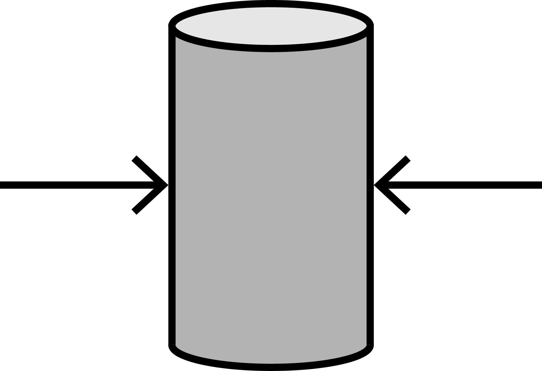 |
| Text and labels | Depending on the material. General recommendations: The hight for the pattern 0,2mm minimum, depth 0,5mm minimum. |
Rules of thumb
- Surfaces in 0-45 degrees angle in relation to the build platform require support structures.
- The recommended max size for round holes without support structures is 3mm.
- Make the channels and holes self-supporting if possible.
- Make the part as light as possible.
- Round the corners if possible.
Size
At Materflow we employ 3 SLM metal printers, Mlab cusing, EOSINT M270 and SLM 280HL. The size of the build chamber dictates the max size for printed parts:
| Mlab cusing | 90mm x 90mm x 80mm |
| EOSINT M270 | 250mm x 250 mm x250 mm |
| SLM 280HL | 280mm x 280mm x 250mm (350mm) |
About support structures
Support structures are used in metal printing to support the part while printing and also for conducting the heat away from the body. In principle every part should be designed so that it’s easy to support since all the supports will be modeled in place according to the printer. The supports are printed with the part connecting the part to the printer’s build platform. The supports are removed after printing in post processing so their number should be minimised wherever possible. Also the surface quality is affected by the supports but this can be dealt with different post processing techniques.
All the surfaces that are in 0-45 degrees angle in relation to the build platform require supports. For quality control surfaces with 45-55 degrees should also have supports since 45 degrees is still a critical angle. Image 1 shows a supported part attached to the build platform. The colors indicate the angles in relation to the build platform.

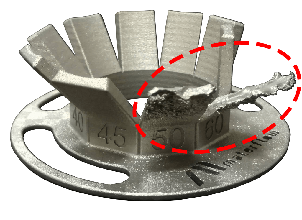
If any critical surface is missing supports the surface can collapse (Image 2). In worst case scenario a single collapse can stop the whole production run.
Limitations
Orientation
When designing a part always consider orientation. Orientation plays a key role in printing and in surface quality. In general the upskin surface has better quality compared to the downskin. Usually the downskins require supports which affects the surface quality even more.
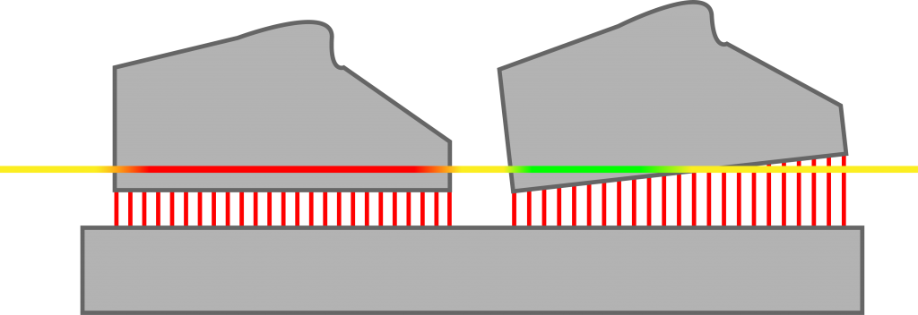
It is advised to tilt the part in relation to the X and/or Y axis to minimise the amount of layer area to fuse when printing. This also minimises thermal stress and warping effect. In Image 3 the horizontal line depicts a single build layer. The image shows how the object on the lefthand side is affected more by thermal stress (the red part of the line) because the laser fuses more material simultaneously. The tilted object on the righthand side is less affected.
Holes and channels
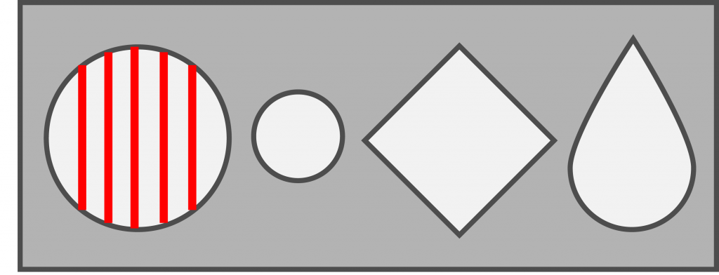
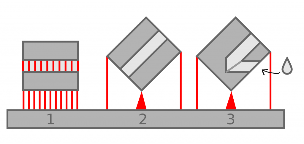
Internal channels must be taken into consideration when orienting a part. In some cases it is difficult or even impossible to remove internal supports so the channels should be self-supporting and/or in 45-90 degrees angle in relation to the build platform. Channels shaped as drop, diamond, ellipse and triangle are self-supporting.
Image 4 shows how a round hole with a diameter over 3mm needs supports. Shorter holes can be drilled to remove the supports but with longer internal channels the removal becomes difficult. The drop shaped profile is self-supporting and doesn’t need supports. With different shapes the walls should be at least in 45 degree angle in relation to build platform. The higher the angle, the better the surface quality and less margin for errors during printing.
Holes and channels with threads should be printed vertically without supports. Usually the threads require post processing with a thread tap after printing.
Image 5 shows three options to support a channel over 3mm in diameter. Option 1 requires supports which affects the surface quality and increases the workload in post processing. The downskin has too many unnecessary supports and the horizontal orientation causes too much thermal stress on the large surface which can cause warping.
Option 2 is an optimal way to orient and print the object in question. Since the surfaces have an angle over 45 degrees in relation to the build platform the downskin and internal channel won’t require supports. The supports are only needed on the bottom edge and on the sides to keep the object in balance.
Option 3 depicts a similar object with a channel in a different angle. In such cases it is advisable to design the channels to be self-supporting i.e. a drop shape or similar instead of a round one.
Optimise your model for 3D printing
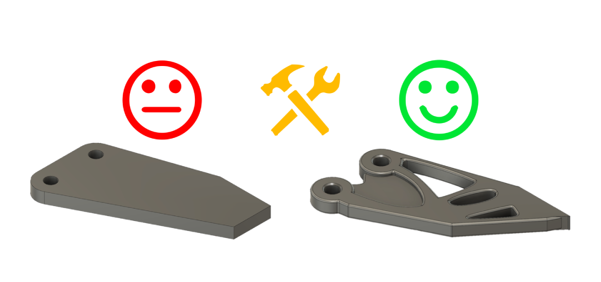
Make the part lighter
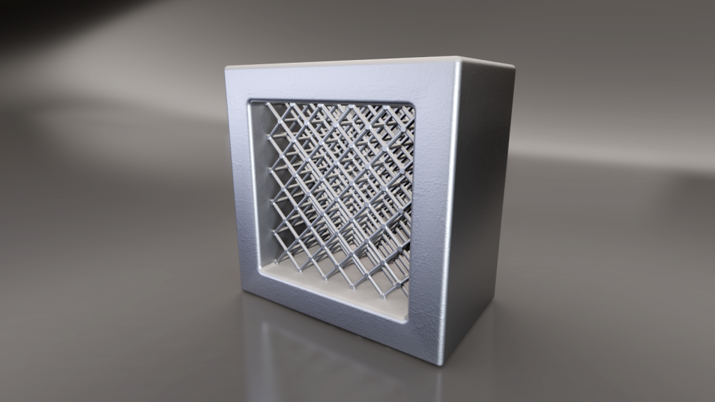
To cut production costs your parts should be as light as possible. This can be achieved by designing the parts so that the raw material is only used/added where it’s actually needed. Printing hollow parts has some limitations since the structure usually needs inside supports. In these cases self-supporting surfaces work very well. Image 6 shows two versions of a hollow object. The first one has surfaces that need supports. The second is fully self-supporting. It is also advisable to have at least one hole over 2mm in diameter to ease the removal of excess and unfused powder in post processing.

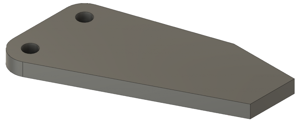
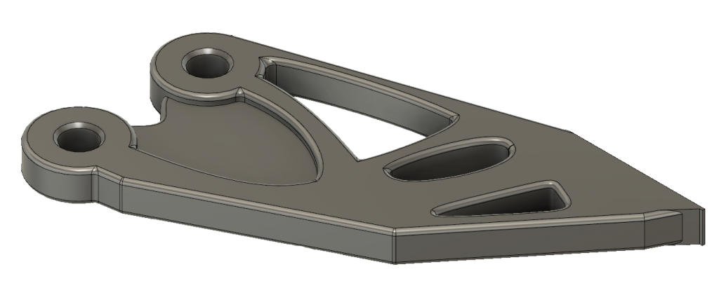
With some modeling softwares you have the option to perform a load simulation and a stress simulation. This so called topological optimisation helps to identify the surfaces and areas that won’t add value to the parts mechanical performance and therefor only add unnecessary mass. Topological optimisation depicted in images 7-9.

Rounding the corners and edges
Rounding eases the thermal stress that usually accumulates on the sharp corners and edges during printing. If possible it is advisable to round off sharp corners and edges since it also increases the parts mechanical durability in general.
Metal printing is gaining popularity
3D printing metal components, spare parts, tools etc. has slowly but surely increased its significance as a production method throughout industries all over the world. 3D printing can simplify supply chains, bring substantial savings on logistics and decrease factory downtime with on-demand spare part delivery. At Materflow we are constantly developing our offering and processes to match the different material and technological requirements our customers have.
Read more about metal printing (SLM – Selective Laser Melting)
Read more about metal print materials


